|
|
|
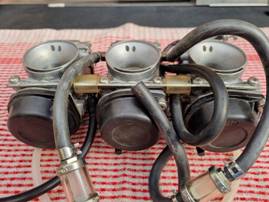
T300 Mikuni Carburettor
Maintenance |
|
|
|
|
Dismantling |
|
|
|
|
|
|
|
|
|
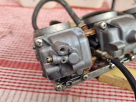
Start with the lower components that are accessed via the float bowls |
|
|
|
|
||
|
|
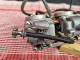
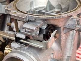
For cylinder 1 (only) it will first be necessary to remove the idle
adjuster bracket |
||
|
|
|
||
|
|
This will then enable you to remove the two Phillips screws holding
the float bowl on to the main housing |
||
|
|
|
|
|
|
|
|
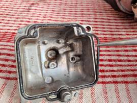
Remove the rubber sealing gasket from the float bowl for later
cleaning and inspection |
|
|
|
|
|
|
|
|
|
Next, carefully remove the float assembly. It is firmly seated in
place by means of two sealing O-rings. Lever the assembly gently and evenly
from points close to both sealing points to detach it from the main housing |
|
|
|
|
|
|
|
|
|
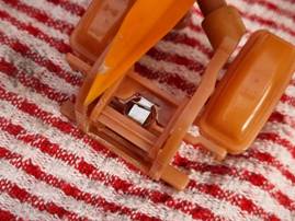
The float assembly can then be disassembled into its components parts.
Carefully and gently prise the outer frame plates slightly apart, just enough
to pull the inner float frame pins out of their pivot holes |
|
|
|
|
|
|
|
|
|
With the two float frames separated, you will now be able to extract
the float spring valve from its seating |
|
|
|
|
|
|
|
|
|
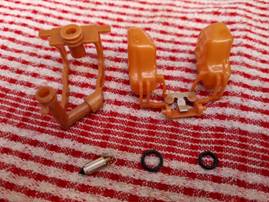
After removing the two sealing O-rings from the outer float frame
legs, you should have all the separated float assembly components as shown
here |
|
|
|
|
|
|
|
|
|
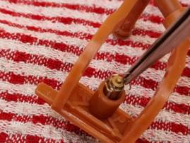
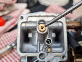
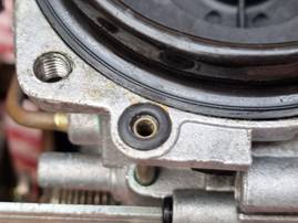
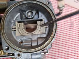
With the float assembly removed, you can then access the pilot jet as
shown here. Carefully unscrew and remove the brass pilot jet using a small
slotted screwdriver |
|
|
|
|
|
|
|
|
|
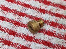
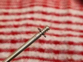
This is what the pilot jet looks like once removed. Its size will be
stamped on the side of its shaft. It is good practice to keep a record of all
jet sizes used for future tuning reference |
|
|
|
|
|
|
|
|
|
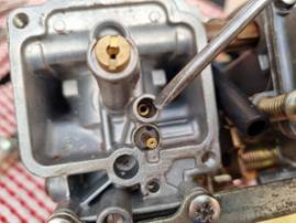
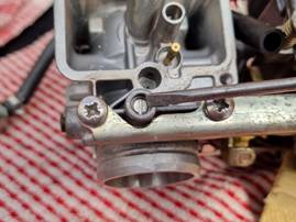
Next to be removed is the main jet as indicated here. Use a larger
slotted screwdriver to carefully unscrew and remove the main jet |
|
|
|
|
|
|
|
|
|
Once removed, this is what the main jet looks like. Its size will be
stamped on the top of its head. Keep a record of this jet size too |
|
|
|
|
|
|
|
|
|
The pilot air screw assembly is next to be
removed. |
|
|
|
|
|
|
|
|
The adjustment position is measured by how many “turns out” the pilot
air screw is from when it is fully wound into its CLOSED position. To assess its current adjustment, slowly and carefully SCREW IN the
pilot air screw and COUNT the number of turns (including any fraction of
complete revolutions) until it JUST closes. This is best done in half-turn
increments. STOP as soon as you feel it close. DO NOT OVERTIGHTEN as this
will damage the carburettor. Once you have taken this measurement and
recorded it, unscrew the pilot air screw all the way out and remove it from
the housing |
||
|
|
|
|
|
|
|
|
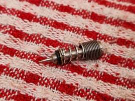
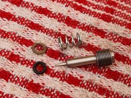
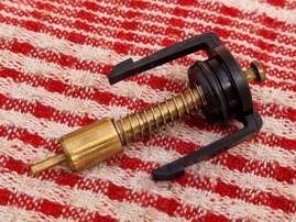
If the pilot air screw assembly comes out as a complete unit, it
should look like this. Sometimes, some of its components can remain inside the
housing, in which case you will need to carefully use a small hook to
retrieve any missing parts |
|
|
|
|
|
|
|
|
|
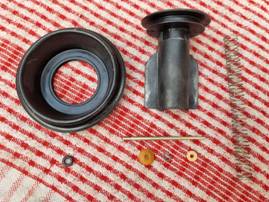
Once you have completely removed the pilot air screw assembly, you
should have all these component parts |
|
|
|
|
|
|
|
|
|
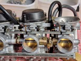
You can now turn your attention to the components parts accessed from
the top of the carburettor |
|
|
|
|
|
|
|
|
|
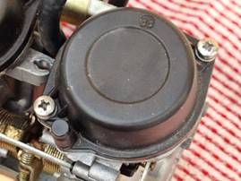
Remove the two Phillips screws securing the carburettor top cover, and
carefully lift it off of the main housing |
|
|
|
|
|
|
|
|
|
Remove the diaphragm return spring from the carburettor slide |
|
|
|
|
|
|
|
|
|
With a small hook, retrieve the vacuum take-off O-ring seal, then
remove the complete diaphragm and slide assembly from the main housing |
|
|
|
|
|
|
|
|
|
This is what the complete diaphragm and slide assembly should look
like, along with the diaphragm return spring and vacuum take-off O-ring seal |
|
|
|
|
|
|
|
|
|
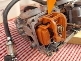
Push the jet needle up and out of the slide assembly, along with its
spacers. Shown here is the needle position clip. Before the clip is removed,
its position should be recorded along with the jet size information for
future reference. |
|
|
|
|
|
|
|
|
There are FIVE clip positions, and they are enumerated from top to
bottom. In the picture shown above, the clip is in position FOUR, as it is in
the fourth slot down from the top |
||
|
|
|
|
|
|
|
|
Carefully remove the diaphragm from the slide body. Shown here are all
the parts that make up the slide assembly |
|
|
|
|
|
|
|
|
|
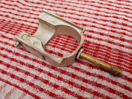
Next to be removed from the main housing is the plastic slide guide
shown here |
|
|
|
|
|
|
|
|
|
The bottom of the slide guide is anchored by the needle jet. If the
assembly cannot be easily prised out by hand, from underneath the carburettor
housing place a small slotted screwdriver up inside the main jet aperture and
gently tap it loose. |
|
|
|
|
|
|
|
|
|
Once fully dismantled, these are the component parts of the slide
guide assembly you should have |
|
|
|
|
|
|
|
|
|
The final assembly to remove from the carburettor housing is the choke
needle as shown here |
|
|
|
|
|
|
|
|
|
But before you can proceed, you will need to remove the choke actuator
bar which links the choke needles of all three of the carburettors |
|
|
|
|
|
|
|
|
|
The choke actuator bar is secured by two plastic clip inserts that
slide into their restraining lugs |
|
|
|
|
|
|
|
|
|
Use a slotted screwdriver to push both of these plastic clips
laterally out of their lugs to release the actuator bar. It should then be
able to be lifted away from the carburettor housing |
|
|
|
|
|
|
|
|
|
The choke needle assembly is released by pressing in towards its
centre the two black plastic retaining lugs at the rear of the unit in the
housing. This is what your removed assembly should look like |
|
|
|
|
|
|
|
|
|
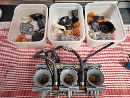
Repeat the above steps for carburettors two and three, and store their
components in separate storage boxes as illustrated here |
|
|
|
|
|
|
|
|
|
||
|
|
|
|
|
|
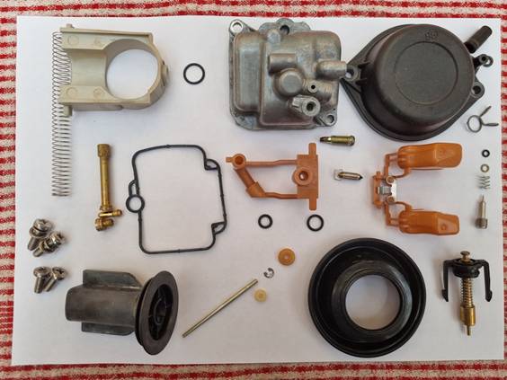
As a final check, you should have ALL the above group of components
for EACH of your carburettors in their storage box |
|||