|
|
|
T300 Mikuni Carburettor
Maintenance |
|
|
|
|
Reassembling |
|
|
|
|
|
|
|
|
|
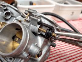
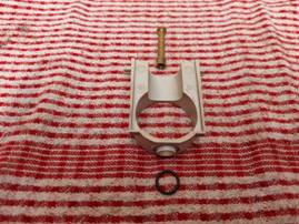
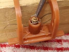
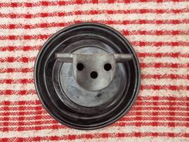
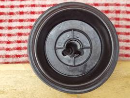
For the first carburettor, reinstall the choke needle assembly. Ensure
that it is fully seated, and that the retaining lugs are fully secure. Test
the mechanism by pulling and releasing the choke pin |
|
|
|
|
||
|
|
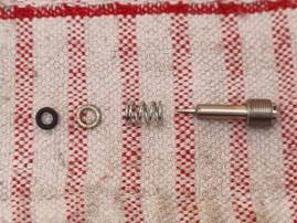
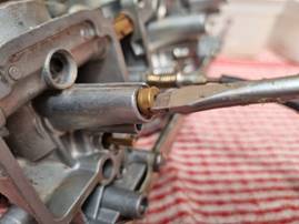
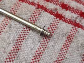
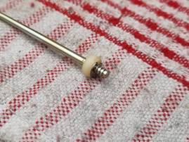
Next, reassemble the pilot air screw assembly. The components should
be loaded in this order |
||
|
|
|
||
|
|
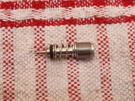
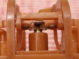
This shows a correctly assembled pilot air screw |
||
|
|
|
|
|
|
|
|
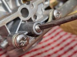
Carefully insert the pilot air screw into the housing, and screw
gently all the way until it is fully closed. Based on your tuning records,
then REVERSE the screw out the requisite number of “turns out” using
half-turn increments |
|
|
|
|
||
|
|
Note that the screw thread itself is very fine and the metal of the
housing is very soft. If you feel ANY undue resistance whilst installing the screw
STOP immediately. REMOVE the screw ENTIRELY. Check that there is no dirt on
the screw or inside the aperture. If there is, clean thoroughly before
attempting to re-install it again. Failure to do so could irretrievably
damage the carburettor housing thread |
||
|
|
|
||
|
|
|
Next, reassemble the slide guide components shown here |
|
|
|
|
||
|
|
|
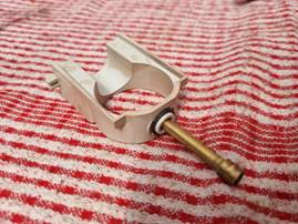
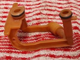
Here is a correctly assembled slide guide. Note the sealing O-ring
secured to its base. The needle jet is installed down through the top of the
slide guide hole and sits flush in a recess |
|
|
|
|
||
|
|
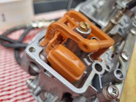
The slide guide must now be lowered into its position from the top of
the carburettor. Take careful note of the correct guide orientation, as it
will only properly fit one way round. |
||
|
|
|
||
|
|
|
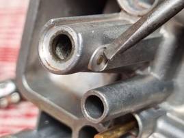
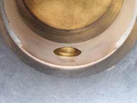
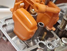
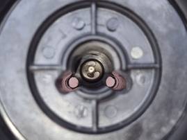
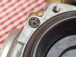
Note the sunken brass pin highlighted here. This pin serves to lock
the needle jet in its position internally to prevent it spinning when the
main jet is screwed in. |
|
|
|
|
||
|
|
|
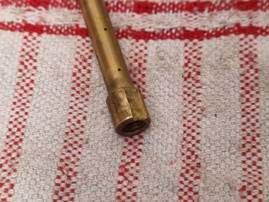
If you look at the lower collar of the needle jet, you will see a
milled flat face on one side. This MUST be aligned with the brass pin, otherwise the needle jet will not be able to be
seated correctly. |
|
|
|
|||
|
|
Therefore when installing the slide guide assembly, particular care
must be taken to ensure the needle jet is in the correct orientation to the
guide, and that it is lowered in carefully to keep the jet correctly aligned
with the pin |
||
|
|
|
||
|
|
|
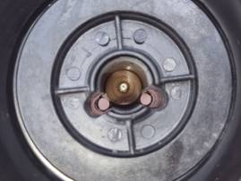
When they are correctly installed, the top of the needle jet will sit
flush inside its recess of the slide guide as shown here |
|
|
|
|
||
|
|
|
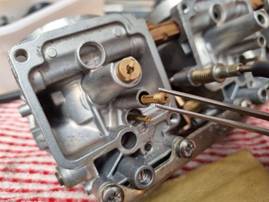
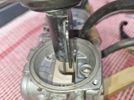
Next, using a large slotted screwdriver, install the main jet. This
will also serve to secure the slide guide and needle jet in place |
|
|
|
|
||
|
|
|
Then install the pilot jet into the adjacent aperture on the housing,
and tighten carefully with a small slotted screwdriver |
|
|
|
|
||
|
|
|
Now turn your attention to the float assembly. Install the two sealing
O-rings onto the outer frame mounting points |
|
|
|
|
||
|
|
|
Turn the outer frame over and fit the float valve into its seat.
Position the valve like this |
|
|
|
|
||
|
|
|
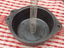
Gently splay out the sides of the outer frame and feed into it the
lower float frame. Seat the two pins into their corresponding pivot holes,
and ensure that the metal spring plate is positioned INSIDE the valve wire
loop |
|
|
|
|
||
|
|
|
Now insert the completed float assembly into the carburettor housing
as shown. Note the extended brass tube of the housing goes inside the front
mounting post of the float assembly |
|
|
|
|
||
|
|
|
Make sure the float assembly is fully seated down in the housing. If
it is, then the flat lugs of the assembly base can be seen to be nestling in
their recesses as shown here |
|
|
|
|
||
|
|
It is important that the float assembly is fully seated in order to
ensure an accurate adjustment of the float height measurement. |
||
|
|
|
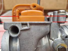
With the carburettor housing turned upside down, the horizontal edge
of the float must be parallel with the mating surface of the housing as shown
by the red lines of this picture |
|
|
|
|
||
|
|
By bending the metal spring plate of the float assembly very slightly
up or down, the float position can be adjusted. Each time an adjustment is
made, flip the housing over and back to let the float settle in its new
position. Check that the float assembly remains in its correctly seated
position at both ends in the housing every time a measurement is assessed. |
||
|
|
|
||
|
|
|
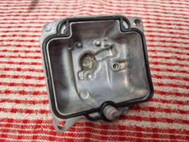
Next, insert the rubber gasket into the float bowl mating edge, and
make sure it is seated into the recessed channel and is fully flat |
|
|
|
|
||
|
|
|
Then fit the float bowl back onto the carburettor housing, and secure
with the two Phillips screws |
|
|
|
|
||
|
|
|
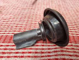
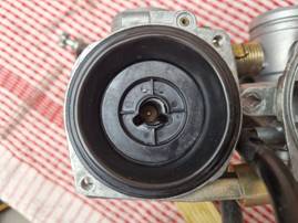
Now fit the diaphragm back onto the slide and ensure that the seating
ring is sitting snugly and squarely in the slide’s channelled recess |
|
|
|
|
||
|
|
|
If the diaphragm is fitted correctly, it will look like this from the
underside of the slide... |
|
|
|
|
||
|
|
|
... and appear like this from the top of the slide |
|
|
|
|
||
|
|
|
Next, fit the clip to the correct position on the jet needle as per
your tuning instructions recorded previously |
|
|
|
|
||
|
|
|
Slide the white nylon spacer up the needle to sit flush with the
underside of the clip |
|
|
|
|
||
|
|
|
Carefully drop the needle down inside the slide recess, so that the
needle protrudes out of the bottom through the centre hole |
|
|
|
|
||
|
|
|
Then drop the orange spacer down the same recess, to sit squarely on
top of the needle as shown here |
|
|
|
|
||
|
|
|
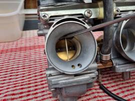
Turn the carburettor housing the right way up, and lower the slide
assembly down into the plastic slide guide. Make sure that the jet needle
drops into the needle jet opening inside the carburettor throat |
|
|
|
|
||
|
|
|
With the slide fully inserted, check that the diaphragm’s upper
sealing edge is seated snugly and squarely in the circular recess on the top
of the housing |
|
|
|
|
||
|
|
|
Fit the vacuum take-off sealing O-ring into its recess on the top face
of the housing |
|
|
|
|
||
|
|
|
Take the carburettor top, and placing it upside down, fit the
diaphragm return spring onto the central locating spigot |
|
|
|
|
||
|
|
|
Turn over the carburettor top and lower it down onto the top of the
housing, ensuring that the lower end of the spring locates correctly into the
slide’s central needle recess |
|
|
|
|
||
|
|
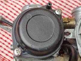
Check that the carburettor top is correctly aligned with the vacuum
take-off tube. When the position is verified, fix the top carefully to the
housing using the two Phillips screws. Do not over-tighten. Check the top
sits uniformly flat on the housing all the way around so that the diaphragm
chamber is fully sealed |
||
|
|
|
||
|
|
|
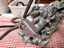
To verify that the slide and diaphragm assemblies are installed
correctly, you should be able to smoothly lift the slide all the way to the
top of the carburettor throat, and when released it should fall back smoothly
to its closed position |
|
|
|
|
||
|
|
Repeat all of the above steps for carburettors two and three |
||
|
|
|
||
|
|
|
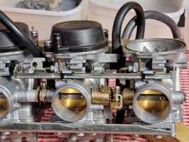
Next, replace the choke actuator bar, ensuring that it locks into all
three choke needle pins correctly, and secure it by sliding the two plastic
clips laterally into their restraining lugs. Pull the actuator bar to test
the chokes move freely |
|
|
|
|
||
|
|
|
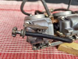
Finally, re-attach the idle adjuster bracket to the base of
carburettor one using its Phillips screw |
|
|
|
|
||
|
The carburettors are now ready to be re-installed on the bike and
balanced |
|||